Favourite Photos...

Favourite Photos...
Reading Lines GP35 #3647

Middletown, Pa

Friday 31 October 2014

First Operational Digitrax SE8C for signalling...

Yesterday I finished off installing the first Digitrax SE8C onto the layout.  It has been located on what will be known as South Bend Curve (a purely fictional place) that is located in the L&T Branch area and interchanges with the new staging yard.

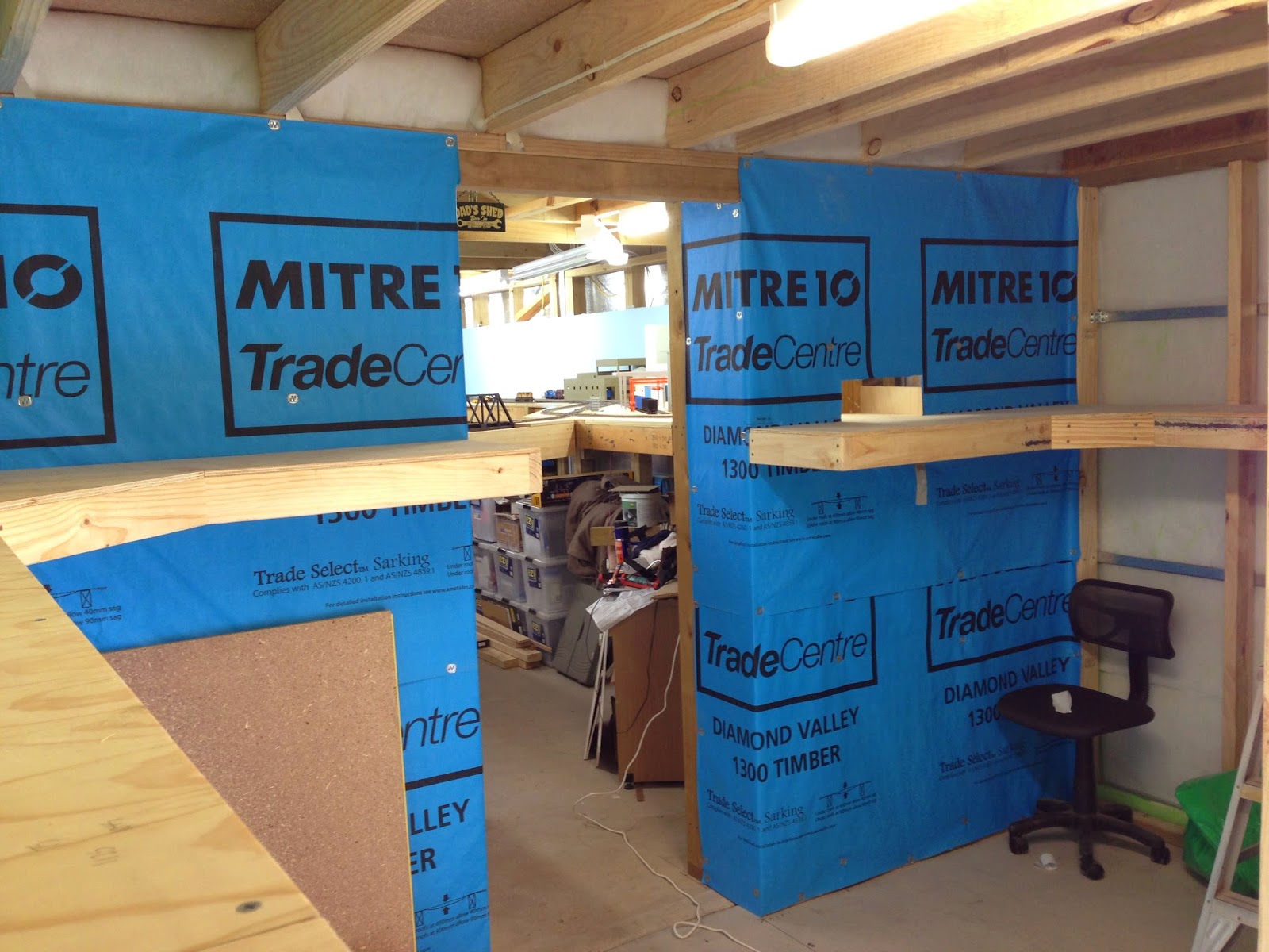
I installed it here because there are a series of turnouts that are behind structures, and also hard to get to.  They are also Walther's Shinohara turnouts that require either a manual throw (caboose ground throw) or electronic like a Tortoise Motor.

So far I have installed the backing board with SE8C and screw terminals and connected three (3) Slow Motion Turnout Machines (SMTM).


The board is placed roughly in the middle of the cluster of turnouts, the SE8C has the ability to control eight (8) Tortoise type switch machines.


The most important thing that I can suggest to anyone considering or about to embark on the installation of signals, is to clearly mark EVERYTHING!!  I have the Digitrax SE8C wiring diagram for the 44 Pin Connector right next to backing board, which is also clearly marked with what wires go to the SMTM & Push Button Switches.

Once the SMTM & Push Buttons are connected I mark the backing board with a common naming convention related to the turnout.  This is as suggested by Digitrax and is also used in JMRI to name the individual turnouts too, I use LT#--, this being Local Turnout & the turnout number, followed by B#-- this representing the Board Number in the system.


When labelling the push button switches I also use the same LT number so that it is easy to identify which switch operates each turnout.  I also place the turnout number on the SMTM too.

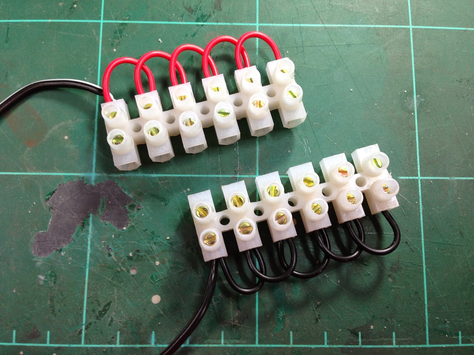
I have also converted the fascia panels with the momentary (normally open) push button switches.  These are extremely easy to install both ion terms of wiring and into the fascia compared to the toggle DPDT switches.


So far the installation has gone extremely well, with no major issues either.  I have had to replace the +VE Common wire for the push button switch power as the connection was dodgy.  But apart from that all good, there is a huge amount of work in installing signals, but it is also very satisfying to see everything coming together and operating.

Next step is to install the remaining SMTM for this SE8C and then work on installing the LocoNet.

Jas...

Wednesday 29 October 2014

Signalling Backing Boards...

Last night and today I finalised the layout of the backing boards for the Digitrax SE8C Signalling Boards.  These boards will operate the signal heads on the layout and also operate the Slow Motion Turnout Machines (SMTM) via Push Button Momentary Switches on the fascia panels and via JMRI and the CTC dispatch panel that is to be completed.

The backing board requires three (3) distinct types of connections to be placed to allow wiring to connect to the 44pin connector that attaches to the SEC8.  

These are as follows:

1.  Two power leads to each of the eight (8) SMTM (16 wires in total).
2.  One lead to each of the push button - momentary switches (8 wires in total).
3.  One lead from each of the push buttons, to the common wire (8 wires in total).

The boards need to be set out in a logical manner to make the initial wiring easier as well as assisting with fault finding if needed later on.  So a clear layout, that is well labelled is essential.

So below is Mark1 for the SE8C Backing Board...


The 44 pin connector (to the SE8C) is placed directly in the middle of the backing board,  its is spaced off the surface of the board with two (2) washers to allow the board to be removed and replaced easily from the connector.  The black eight (8) terminal block is for the common wire for the push button/momentary switches and saves having to "loop" a standard terminal eight times.

The wire that I will be using for the connections between the SE8C and the terminals will be CAT6 Data cable.  I prefer this as it is solid core instead of stranded, I will also be using this to wire between the screw terminals and the SMTM's and push button switches.


So far I have wired in four (4) pairs of the SMTM paired power wires, and have another twelve (12) to go.  Then it will be onto the eight (8) power leads for push button switches, this will finish off the connections to the 44 pin connector.

UPDATE:

So after another two (2) hours last night I have finished the first of the SE8C boards, not really that much of an issue doing all the wiring and soldering.  I will say this however you need to take a lot of care just before you solder, I guess its like the "measure twice" rule always check the orientation of the wires and the placement before soldering to the connectors.


Having the extra space and laying out the screw terminals in a logical way will help later of for any fault finding or adding extra features (to be controlled by JMRI) will be easier.
 

Using the CAT6 Data cable IMO is the best way to go, the solid nature of the wire makes it easy to work with, bend and form paths around the boards and is really cheap.


Another six (6) SE8C boards to go, then onto the BDL168's.


Jas...

Tuesday 21 October 2014

Workbench Nook Update...

Yesterday i managed to finish off installing the bench tops for the workbench nook & dispatcher area.  The bench tops are 18mm MDF that has been coated with satin finish Cabothane.  This will help protect the tops from moisture and spills.


I also installed the storage bins that I picked up about a year ago, these are in addition to the existing units I already had.  Due to expansion and the extra storage space on the wall I'm now able to add them.


The dispatch area is ready for the twin monitor bracket (yet to purchase) and the keyboard & mouse for the JMRI PC.  I'll be using a wireless pair to save having to route wires back through the benchwork or walls.


The small piece of MDF (which is also coated in cabothane front & back) is installed over the bench work and will be used for when I need to either paint, airbrush, or weather locomotives, rolling stock & buildings.  I have a self healing mat on top of this as well, I will eventually be getting a portable spray booth for this area.


Next stage will be to install the remaining storage bins (existing) and begin placement of the dispatcher gear including the PC and twin monitors.

UPDATE...

And at the end of yesterday this is what we finished with, just about all of the storage in place and filled again.  More room, better layer out, more bench space & a dispatcher area too.


More soon,

Jas...


Monday 20 October 2014

Building up the Hardware...

Over the past month I have been beginning to collect all the necessary hardware to begin the signalling installation for the layout.  To date I have two (2) Digitrax SE8C's for Tortoise Switching & Signal Heads, one (1) Digitrax BDL168, five (5) double head - searchlight masts, five (5) single head - searchlight masts, five (5) of each single & double head dwarf signals all from Tomar Industries.
I have the power supply for the SE8C's which is a 15V - 2A transformer which will run us a layout buss for all of the SE8C's, I have also ordered the RR CirKits LocoBuffer USB to interface the standalone Loconet with JMRI through the layout PC.
I have also ordered another twelve (12) Tortoise motors, bringing the total to 30.  It should be noted that the totals mentioned in this post only refer to being able to detect, switch & signal the main.  In order to do all three on the entire layout and include all passing sidings and spurs it will require seven (7) SE8C's five (5) BDL168's 50 Tortoise Machines, 50 Signal Masts/Dwarf Heads, the layout will be broken into 73 blocks.
Below is the new signalling plan for the 73 Blocks, this number has increased after discussions with my good friend & signalman Brendan after we discussed the advantages of have each turnout as its own block.

When you look at the totals and start thinking about price it becomes a major investment, it's almost the biggest if not the second biggest for a layout.  Our layout is also by no means a large layout, and there are still extra costs to be factored too.  I have twin monitor screens to purchase (for the CTC/JMRI panel), there is added electrical work to be done for the JMRI PC, the hundreds of feet/metres of CAT6 cable, momentary SPST switches for the panel mounted fascia's, and the list goes on......
Hopefully towards the end I'll be able to break it all down and give a true cost analysis of the project, and by posting threads of each section give those contemplating it a better understanding of the process involved trying to get there.  More soon...
Jas.

Tuesday 14 October 2014

Dispatcher Area & Work Bench Nook - Update...

More progress today on the Dispatcher Desk & Work Bench Nook.  I installed all the bench frames for both sides, the dispatcher desk is 1400mm (4' - 7 1/8") x 400mm (1' - 3 3/4") and is on the left hand side.  This will have the two screens for the JMRI - PanelPro CTC Panel, keyboard & mouse, and whatever communication system I install for the layout.
The Work Bench wraps around in an L shape from the right hand side and back across the middle.  The right section will be for everything to do with building, assembly, maintenance, soldering, etc.  It's 1400mm (4' - 7 1/8") x 500mm (1' - 7 11/16") and will also have a MDF top.  The middle section will be for painting, weathering & detailing (I'm purchasing a mobile spray booth at a later date) this section will have a further 3mm sheet of MDF or Cork over the bench top so that when it is completely shot, and covered with  paint it can be replaced.
The bench height is set so that the roller chair can be spun to either side without hitting knees or legs on any of the frame, there is enough room to have two chairs in the space (although tight) or one person on the dispatch deck and one operating the Diesel Service Facility above.  The chair can also be rolled out into the crew lounge area so that operators can get straight out of the chair clear of the nook.
I can see myself spending quite a lot of time in here, it's quite cosy and will be a good place to work on locomotives & rolling stock when I begin weathering.
This wall will be for all of my storage bins, parts pins, tool racks, etc.  I've amassed a fair amount of cheap storage units that will no doubt be filled in the years to come.  I will be installing two quad power points (receptacles) along the wall for tools like Dremels, Soldering Stations, iPhone Chargers (music), and will also have some form of adjustable lighting as well.
In all I'm really happy with the way the "nook" has turned out, it's amazing what you can think of that needs to go into a well functioning work space, and then to throw in a dispatch area as well takes a bit of thought and planning to pull it off.
Next stage is to finish off the dispatch & work area bench tops.  These will be coated with a water based clear sealer to protect the MDF, more soon.
Jas...

Sunday 12 October 2014

Signalling Plan...

Here is the work in progress signal plan for the layout, it incorporates the new extension and is roughly blocked.  This is by no means the final version as myself and Brendan have some work to do fine tuning it.
The main is fully signalled, and the passing sidings will be to, but mostly with dwarfs.  It needs to be noted that I'm not following a prototype system, I'm not overly concerned if it also doesn't follow the RR's signalling systems that I'm modelling too.
We have decided to base the system around operationally what will work for the layout and its operations sessions.  So if you pick up that there are signals missing from places that normally would have signals, thats fine we have countered it in our plan to have plant protected in groups in places.  This significantly cuts down on blocks,  signals and the hardware required for detection & signalling.
The next stage is to install all of the Tortoise Switch machines on the mainline, then connect these to the SE8C's via push button, momentary switches and get these working through JMRI.  After this we will be looking at the wiring for the entire layout and reconfiguring this to work in with the common rail power for detection.
Jas...

Saturday 11 October 2014

Dispatcher Area & Work Bench Nook...

As part of the expansion of the layout into the new area I have decided to move the current workbench area into the new extension.  Along with this, the future dispatcher desk will also be incorporated into it.

The current location in behind the centre peninsula, and with the operating area of the L&T Branch is just a little tight.  The new area although small is serving a dual purpose and will work a lot better than the previous one, the ability to have separate dispatcher desk, work bench & spraying/building area will be a great little addition.


I've decided to add a small computer alcove to the dispatch area, behind the wall is a void underneath the return blob/paper mill area.  This will provided really good access to all the electrical components & hardware for the layout.
I will install a hinged panel and attach the main layout power distribution system to it, and also have the DCC Command Station within the computer alcove too.


The first stage of the nook is to add the back board which is 12mm MDF, and is for the dispatcher wall.  This will have the twin screens for the JMRI Panel on it as well as other information for the layout for the dispatcher to control.  Directly underneath the back board will be the dispatcher desk.

The next stage is to install some electrical points and then continue on with the back boards.

Jas...


Trackwork Benchwork Finished...

Yesterday I had another full productive day of finishing off the benchwork for the new extension trackwork (staging yard & diesel serving facility) the plywood base is down and secured all that remains is to add the final sub roadbeds of drywall/plaster & cork.

Staging/Classification Yard on the left & Diesel Service Facility on the right...


The benchwork for the Classification Yard sits above our storage shelves, these will eventually have drop curtains fitted to the underside of the timber frames that overhang the shelves by about 90mm.


The penetration through to the existing L&T Branch area has been completed, and I have installed side guards to the crossover bridge to protect any locos or rolling stock that if derailed in the void would take a long drop to the concrete below.


The Diesel Service Facility area is also finished and the benchwork complete, again there is another penetration through the existing layout this time to the interchange connection that will eventually lead down to staging under the layout on the northern side.


Again this penetration through the new extension framed wall & existing shed wall has a void around 1' (300mm) in width that has been bridged, I also added a side guard incase of derailment stopping that drop down to the concrete floor below.


And looking back from the existing layout to the new Service Facility...


More soon...

Jas.

Thursday 9 October 2014

Layout Expansion - New Track Update...

Well today was a very productive day, seeing the new staging area benchwork almost finished, all that is left is a small section of plywood and the drywall/plaster & cork to be laid and its ready for track.


The above section still to have the plywood installed with have the yard lead to the new staging, from the centre peninsula turnout just before the bridge.  It will also hold a couple of storage tracks & caboose tracks.

Below are the penetrations between the existing L&T area (old staging area) and the new staging area housed in the new extension.  This will connect to the new industrial siding on the south wall and will also help produce the new "wye" for the layout.


Looking from the old staging back into the new staging area...


I also managed to install the bench framework for the new Diesel Service Facility that will be  above the dispatcher/work bench nook.

Diesel Service Facility benchwork installed...


Breakthrough into the existing layout, this will have the lead to the service facility which will connect to the "interchange" track.


More to follow.

Jas...


Tuesday 7 October 2014

New Track Expansion for the JL&T...

Yesterday I began part of the expansion of the trackwork for the JL&T.  With the near completion of the extra 4m (13') of layout room I began the new Staging Area for the layout.

This will be run as a Classification Yard for the major portion of train movements for the layout, it directly connects with the existing staging area located on the south wall of the layout in the L&T area (which will become another narrow industrial area) and forms a Wye with the northbound track leading over the lift our bridge.

The benchwork is 4m x 400mm (13' x 16") and runs on top of the storage shelving in the new extension.  It will hold five storage tracks with two drill leads for locos to escape as the yard is all stub ended.  There maybe a future extension along the east wall the may lead to the yard expanding in length and/or another large industrial switching area.


The benchwork is being made in two modules, the method is the same as employed for the rest of the layout to date.  Pine framing topped with plywood and the Drywall/plaster and cork sheet.


To connect to the existing trackwork I had to make a penetration through the existing shed metal skiing cladding, this will have an insert place inside to stop any wayward locos or rolling stock from falling into the void inbetween the two walls.


The penetrations will be hidden by some form of scenic element like I have used before, either a building, billboard, or bridge.


More soon as we progress.

Jas...


Signalling Adventure Begins...

Over the last week I have started our venture into signalling the JL&T.

The start is only small and involves the installation of a couple of Tortoise Motors to control a series of turnouts that are hidden behind the Cement Plant on the L&T Branch, but none the less it is the start.

There has been a significant amount of research, running ideas through our resident signalling & electronics guru Brendan, the ordering of several pieces of electronic hardware to control it all, and of course the signal masts & dwarf heads.

I'll go into the details later on as we progress, because even though we have a game plan of sorts, it is still fairly fluid as to the final setup.  Needless to say it is based on a Simple Serial Buss (SSB) design and will be working in conjunction with my existing NCE Power Pro - 5amp DCC System.

But back to the newly installed Tortoise motors...


For a temporary fix to a throwing of a series of turnouts while operating the layout, I've installed a few of the Tortoise's and wired them to some DPDT switches.  These will be replaced at a later date with push button switches wired direct to a SE8C and controlled by JMRI.


These are the terminal blocks I have installed to power up the series of Tortoise's in the area, they run off a 12V (adjustable from 9V to 12V) and running 2.5A. gain these are temporary and will be replaced with smaller more reliable terminal blocks and either Cat5 or Cat6 wiring as the standard for the signalling wiring.

This will be run as a 12V buss around the layout to control the Tortoise's.  Again these are temporary and will be replaced with smaller more reliable terminal blocks and either Cat5 or Cat6 wiring as the standard for the signalling wiring.

As part of the installation I also made and installed a small fascia panel for the area too.  This was a draft version, but has turned out quite reasonable and will end up being the standard for all of my panels.  These were done on Pixelmator and laminated then stuck onto 3mm MDF with double sided tape.

The panels and switches will be recessed into the fascia at a later date...


The DPDT switches wired directly to the Tortoise Motors for manual control...


More to come soon as we progress on the signalling...

Jas.