Favourite Photos...

Favourite Photos...
Reading Lines GP35 #3647

Middletown, Pa

Wednesday, 22 July 2015

Installing the Fascia's & Fascia Panels...

Yesterday I began the installation of the fascia panels for the centre peninsula that is the main layout area.  This phase is linked to the detection and signaling install as the majority of the SE8C's are now wired and have push buttons installed to operate the layouts Tortoise Switch Machines.
Continuing on from the L&T Branch fascia & upper valance install I am still using 3mm (1/8") MDF for the fascia.  The ability of the MDF to form curves around corners, it's light weight and cheap cost make it a perfect material to use as a fascia.
The main layout fascia will be 250mm (12") wide and will have recessed fascia turnout panels in it for local switching during ops sessions.  The fascia is secured to the 90mm (3 3/4") pine bench work, the install of this actually goes quite quickly.
Within a few hours several feet can easily be installed, the only part requiring extra attention is when forming curves.  Sometimes there is a need to put back blocking or bracing behind the curves and on seams at joins.
More soon.
Jas...

Saturday, 11 July 2015

RRCirKits SMD Tri-Coloured LED's for Dwarf Signals...

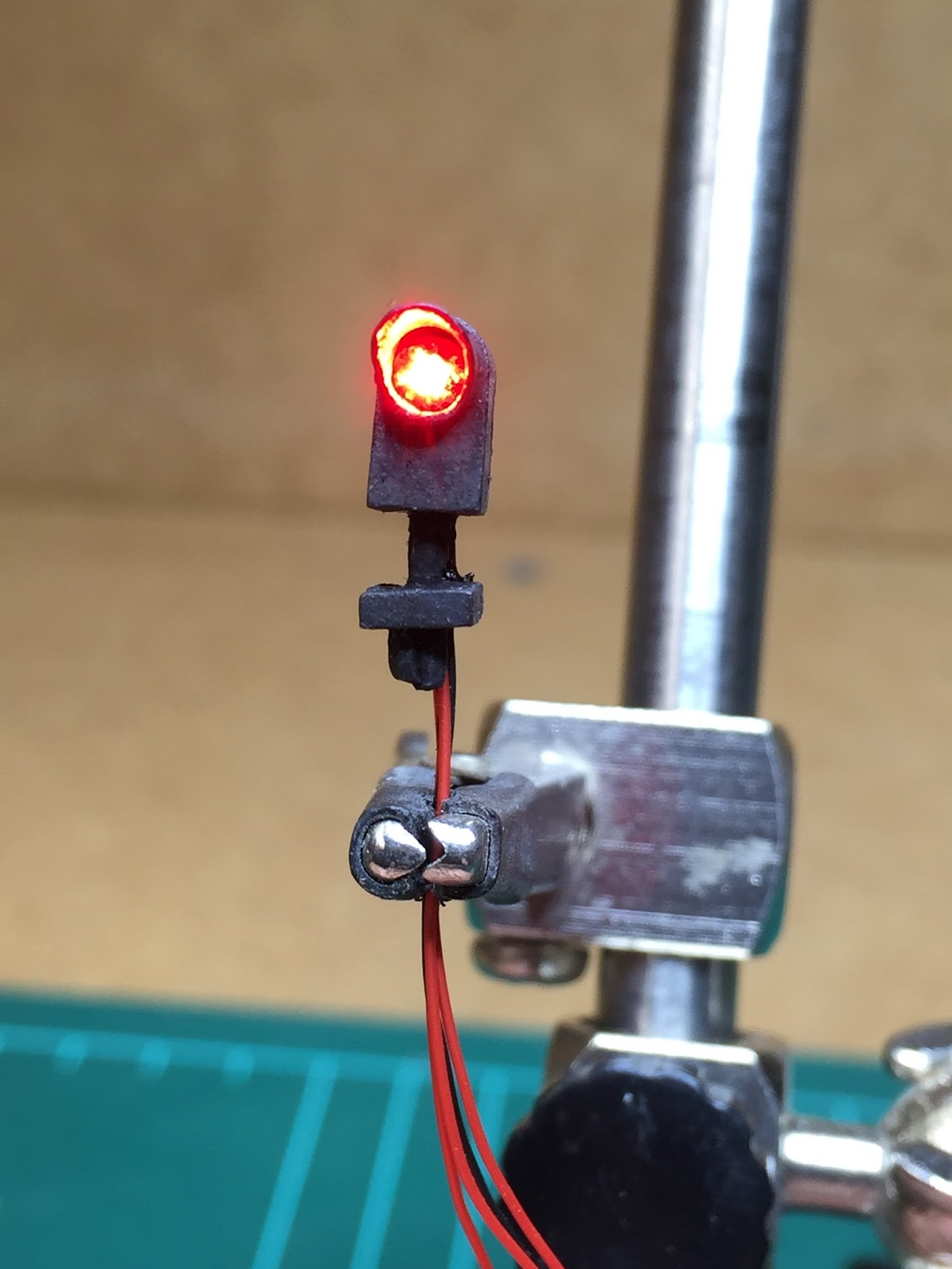
Moving right along with the installation of SMD LED's into our Tomar Dwarf Signals is the installation of a different type of Tri-Colored LED from RRCirKits.

These are tiny 3mm - 1/8" SMD LED's on tiny Printed Circuit Boards (PCB), these are made for RRCirKits and as such have colours that are designed to match real aspect indications.  The brilliant part about these babies is that the LEF comes pre-wired to the PCB with holes already punched for the common & three coloured wires to go in.


Even though these are extremely small, they are actually quite easy to work with.  The PCB holes take 30 AWG wire wrapping wire perfectly, even when slightly tinned too.

When completed the whole PCB fits perfectly into the opening of the Tomar Dwarf Signal.


When installed into the opening in the case, these can be either secured with CA or Liquid Electrical Tape (LET), the tape is perfect for ensuring that the PCB stays in alignment with the opening and prevents any shorting onto the brass case.


These really are the perfect solution to replacing bi-coloured LED's to get a true green, yellow & red aspect colour.
  

Special thanks to Dick Bronson @ RRCirKits for supplying us with these LEDs.
I'll post some more photos soon once they are installed on the layout and operating...
Jas.

Monday, 6 July 2015

Double Head Dwarfs with SMD LED's...

Well after successfully installing the SMD LED into the single head dwarf it was time to move onto the more challenging double head version.

First step was to install the much thinner coated wire, these are around 32AWG.  These wire still have a plastic coating so it is easily removed.  Again I made sure that I pre-fluxed & tinned the SMD pads and wires first to ensure a quick and good bond of the solder.


The next stage was to coat the wired SMD LED with liquid electrical insulation, this is to prevent the SMD pads from shorting out onto the brass case of the Tomar Signals.  The case needed some filing to get the SMD case to fit into position so that light emitted came through the opening evenly.


As can be seen below the Bivar SMD LED fits quite well into the case of the Tomar signal.  The liquid electrical insulation (LEI) also helps to keep the SMD in place and aligned.


Below is the back of the dwarf signal and the LEI holding the the bottom aspect in place.  As can also be seen there are four wires for each LED, one common (black) & three (red) for each colour green, yellow & red.


The stage involved getting the second SMD wired and into the brass case, all of the wiring and both SMD LED's fit into the Tomar case quite well.  The LEI works really well to insulate the electrical connections and hold the SMD LED's in place, for added stability you could also CA them in too instead of relying on the LEI.


After the LEI had cured I powered up the SMD LED's to check there wasn't any shorting from the electrical pads to the brass case, and also to check the colour produced with differing resistors.  The output of these LED's are quite bright and as such could be reduced up to a 1000 ohm value with resistors, this would actually increase the overall LED life too.  

And the final the result...  A Slow Clear (CR1988 Signal Aspects).


Monday, 29 June 2015

SMD LED's for Dwarf Signals...

Well as part of the installation of the signals on the layout I needed to do a little experimenting the last week.  One of there issues I have been facing is the installation of the dwarf signals on the layout.

I have already purchased the single & double head dwarfs from Tomar.  These are fitted with bi-coloured red/green LED's that are capable of producing a yellow aspect as well.  The colour of the yellow is somewhat hit and miss and can take some tweaking to get right.


So time to think about possible solutions to get a true green, yellow & red.  I found a site on FaceBook that was for the LKVMRR (LeHigh & Keystone Valley Model Railroad Museum) http://www.lkvmrr.com.

They have been using a true tri-coloured LED on a small 3mm PCB that fir directly into the Tomar Dwarfs and Searchlight masts.  These are from RR-CirKits and are Dick's own design and built for them, I have several of these on order and on the way over and will post a thread on them when they get installed.

As an interim measure and for the remaining Tomar Searchlight masts that I also have that will be placed around the layout I found these Bivar SMD Tri-Colured LED's to trial.


These are from Mouser Electronics and are available for about $2.50 AUD each.  These have arrived and I have already fitted one out to a single head dwarf signal.  The SMD LED's are extremely small and come packaged in a strip with removable tape.


The process was relatively easy and went without a hitch, the fist stage is to remove the existing Tomar bi-coloured LED.  The case of the Tomar dwarfs is made of brass, and when removing the original LED try to ensure that you leave the black paint as it helps insulate the case against the powered LED terminals.


Once this completed I needed to solder on the feeders for the LED, these SMD's are common anode.  I chose decoder wire to use on the single head signal as it only requires four (4) wires, for the double head dwarfs I'll need eight (8) and more room to get them all in the housing.

Now to say I was a little scared about having to solder these wires onto these SMD LED's was an understatement, but it actually went quite well.


The soldering to the tiny tabs is not that bad, I tin the decoder wire, flux the pads and tin with a small amount of solder first, then touch the iron with both connected to make the final bond.  for the remainder of the SMD LED's I'll be using the magnet wire as it will help with the positioning of the LED in the dwarf case.


Once the wiring was completed I then tested the individual colours to ensure they were working before installing them into the case.

As can be seen the colours are quite clear and distinguishable, the next step was to fit the SMD LED with wires into the Tomar housing.

The fit of these SMD's is quite good the housing is 3.5mm x 2.8mm and the opening for the dwarf fits a 3mm Bulb type LED.  The actually lens diameter fits perfectly within the opening of the dwarf signal housing.

Finally I needed to check the operation and the output with the SMD LED and wiring within the dwarf case.  As mentioned before I needed to ensure the SMD tabs wouldn't short out to the brass case of the Tomar dwarf.

So the results are below...

Green, Yellow & Red Aspects from one Tri-Coloured SMD LED...


Next stage will be to install two of these with magnet wire into the Tomar - Double Head Dwarf Signal.

Jas...

Sunday, 14 June 2015

New DCC Sound Decoder...

Well I've bit the bullet and decided to try a different type of DCC Sound Decoder.

I have been using Digitrax - Tsunami Sound Decoders with all my sound equipped locomotives & switchers.

But after doing a little research and watching a view reviews online I'm sold.  The combination of the manual & prototype notching and the ease of programming is making these decoders very hard not to install.

I've had TCS decoders before (prior to getting into sound) and I have never had any issues with them and they have always been solid performers.

The details of the new decoder that I will be trying is the:  

TCS 1530 WOW101 - Diesel EMD Sound Decoder.

http://www.tcsdcc.com/Customer_Content/Products/Decoders/WOWSound/WOWDiesel.php


Pictures courtesy of TCS website.


This video shows how good the TCS WOW decoders are, and the great sound too...


I'll be coupling the decoder with the TDS Speakers & enclosures that are mentioned in the YouTube video above.  These are all purchased from Tony's Train Exchange...


Pictures courtesy of Tony's Train Exchange.

When they arrive I'll pick a suitable locomotive or switcher from the fleet and demo the installation and the result on this blog at a later date.

Jas...

Wednesday, 27 May 2015

Town Names from the real Reading Area...

In a major milestone the JL&T Railroad has had its functional town names added.  I have to paint a little picture about how this came about so here we go...
For those following along with our build you may recall that I have defined the layout as being proto-freelanced and somewhere in the era of the 70's to late 80's (loosely).  The layout and its areas where to be purely fictional, but the railroads servicing it were somewhat prototypical (they actually existed), and I must highlight the word "somewhat" as the RDG has been allowed to live on in my little world past its Conrail takeover date.
So when I decided to change the intermodal terminal to a Paper & Pulp Mill I didn't actually realise but I was making a very good decision for later on when looking at naming towns for the eventual addition of operations & signaling.
One of the issues I faced when deciding to make the layout a purely switching layout and having regular ops sessions was that I needed to have named towns for it all to come together.  I didn't really think about naming them after specific towns because well the layout was never going to be truly prototypical in that respect.  But along came the decision to add detection & signals, so I decided to look further into it.
One of the caveats for naming the towns was that it had to be an area in Reading Lines, Conrail & Chessie System Country.  It also had to have a Paper & Pulp Mill near it, a place to interchange between RDG & Chessie System as well as working in with Conrail too.
I also wanted a portion to allow point to point traveling between two yards representing two major areas with RDG/CR territory and Chessie System territory too.  Hey not to hard right?  I also decided to add it needed a river crossing (as I have one between decks) and to top it all off I wanted to have Reading, Pa as a town in there as a homage to the Reading Lines/Reading Company era that the layout is based on.
So over the last two weeks I have been attached to Google searching Google maps and looking for areas that would suit all of the above givens & druthers I have placed on this project.  And to my surprise I have managed to pull it all off......
So below are the two main system maps that I have been using to figure it all out:
Reading Lines - System Map...
Chessie System (WM) - System Map...

So for those that know the history or the area the RDG & Chessie System (WM) would have interchanged at Shippensburg & Lurgan, so I now had my interchange sorted between two of the RR's on the layout.  Now upon some further research I was able to find that not far from the interchange area there was a Paper & Pulp Mill at York Haven in Pa, so I now had the P&PM sorted and geographically located on the layout.
Next stage was to add the remaining Reading Lines towns along the system and sort out the yard names for the staging and classification yards.  So after a few hours today I've managed to get the map populated with all the towns, I also have one of the yards named and only have the engine servicing facility to name after I do some more research.
So here is the JL&T Railroad - System Map...
Feedback is most welcome and any links to these areas or photos would be greatly appreciated too.
Jas...

Wiring Tortoise Motors & Fascia Push Buttons to a SE8C...

So this is what a Digitrax SE8C looks like with all the wiring from the Tortoise Motors & Fascia Push Buttons connected...


The above SE8C was wired by Noel Purdy one of dedicated and crazy (because he enjoys wiring) wiring crews.  The fascia push button leads are quite long as this allows us to place them in the middle of this section of fascia, once clipped up to the underside of the layout they will be trimmed to length if required.


Close up view of the connections to the SE8C, there is a colour coding standard to the madness in this photo.


First stage completed, the top terminal block has the power feeds (position 1 & 8) connected.  The clipping of the wiring loom to the underside of the benchwork is because I will have storage under the layout and I do not want anything being caught and/or ripped out if the wiring is hanging down.

Jas...

Wednesday, 6 May 2015

What do you do when it's cold and raining?

More Switch Machine wiring of course...

Today I managed to route all the wiring that had been ran from the last wiring session.  Because underneath the layout will be used a storage I wanted all the wiring to be clipped to the benchwork, and it fulfils my wiring OCD...


For anyone considering adding switch machines and/or detection & signaling to your layout think long and hard about how much you like wiring.  Because there is a lot of it...


I've kept a consistent wiring methodology to the hook up of the various switch machine & push button wires back to the SE8C's.


Jas...

Sunday, 3 May 2015

Industrial Models - O Scale Weathering...

Just wanted to share with you what I can only describe as the most astonishing layout, weathering & detailing I have seen to date...

Don Smith has such an amazing eye for detail, and uses real world photos for all of his weathering & detailing on his O Scale layout and it shows!


I've been looking for inspiration for our layout and the industrial scenes, and I've now found something to reference against.

Don's work can be found here on Facebook:  https://www.facebook.com/oscaletrains?pnref=story

And on his website here:  http://www.industrialmodels.net

Jas...

Wiring night get together...

So last Tuesday night we had another successful wiring night for the JL&T.  Noel & Dennis came over and we continued work on installing the wiring for the fascia push buttons back to the SE8C's and the wiring from the SE8C's to the Tortoise Switch Machines.


Was an extremely enjoyable night catching up over a coffee and chat and working on the wiring, we have just about finished the centre peninsula.

Hopefully after another session or two we can move onto installing the fascia's.

Jas...